LCD Multitouch Table Mark 1
Multitouch is cool, but its also becoming cheaper and more accessible thanks to the work of folks like Jeff Han, and communities like the NUI Group. Of course, devices like the iPhone have made many of these ideas mainstream, but not everyone wants to do multitouch on a tiny display. Multitouch surfaces have great potential as intuitive, multi-user, social computing environments.
I wanted to build a small, portable touch table that can be used by one or two people. The display surface is the horizontal table top, and people "play" at opposite sides. Its a bit like those old-style sit-down arcade games, though for the life of me I can't remember any games that were simultaneous two-player. Both users can touch the surface, but also maintain face-to-face interactions across the table. The device is designed particularly with kids in mind, for play between two children, or between a child and parent.
Design
There are many ways to do multitouch sensing, but the basic idea used here is to measure pressure optically with a camera. A great place to get some background is this thread at NUI group. Since I wanted to do fiducial tracking, I chose an approach based on diffuse illumination. This means that the display does not rely on a very tight coupling with the surface to illuminate objects.
I wanted my table to be small, cheap and robust, so I chose to use an LCD rather than a projector. LCDs don't transmit diffuse IR very well, so the illumination is provided by the surface itself (Diffuse Surface Illumination, or "DSI"). A special type of acrylic (called "Endlighten" or "DLux", depending on the manufacturer) is used as the top surface of the display. This has embedded particles which reflect light out the surface when lit from the side. This material is often used in display signs.
Parts List
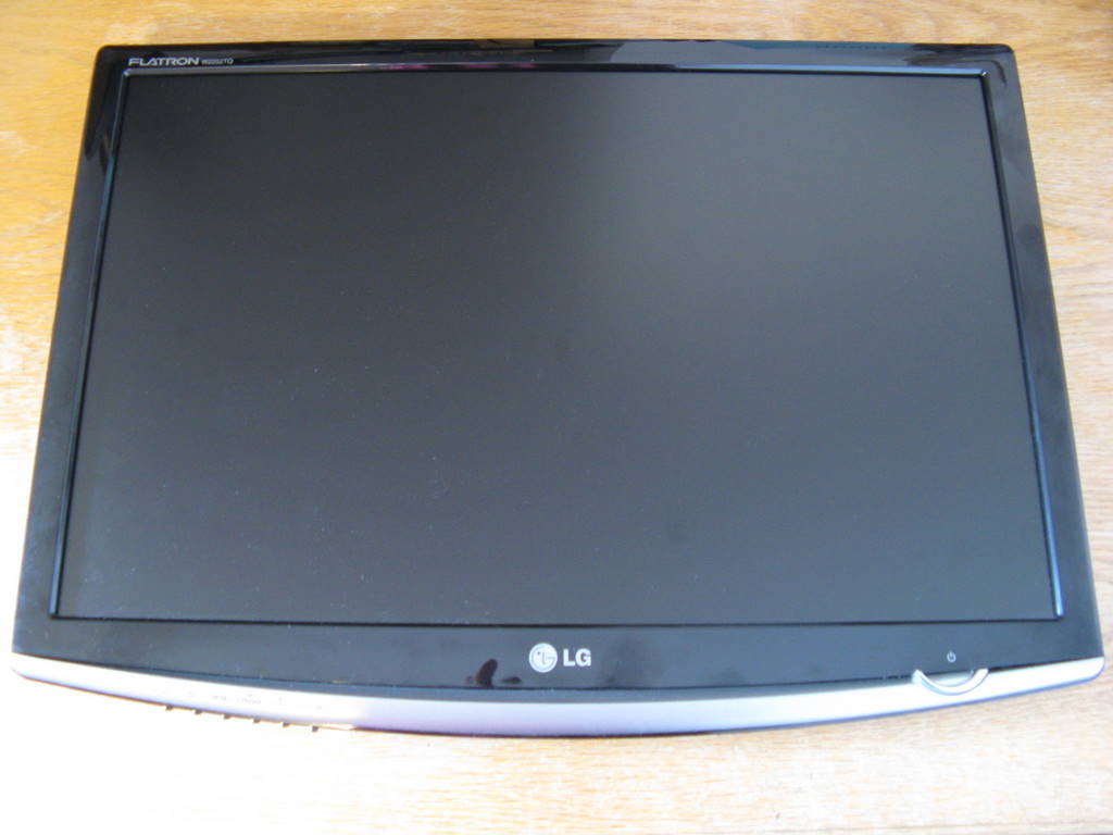
- LG W2252TQ-PFT 22" LCD Monitor
- Unibrain Fire-i B/W Camera
- 2.5mm focal length lens
- Mac Mini
- Firewire 9-pin to 6-pin cable
- IR pass filter 850nm
- Acrylic panel, 10mm "Endlighten"
- IR LED strip illuminator
- Power supply, 12V for illuminator
- Misc hardware: MDF, wood screws, nut/bolts, square dowell, 1" aluminium angle, steel strip, T-nuts, hinge, construction adhesive, silicone sealant, magnetic catches, gaffa tape I found a lot of useful information on-line, but much of it was fragmented. So here is an illustrated guide to how I built my system. Click on the images for higher resolution versions.
Step 1: Disassemble Monitor
I selected a 22" LCD display from (LG W2252TQ-PFT), as these seem to give a good balance between size and cost. I wanted something cheap so that it didn't matter too much if I trashed it.
First problem is to get the thing apart without breaking it. The monitor is held together with pesky snap fittings, so you have to carefully prise it apart with a screwdriver. Hint: if you remove the grey front bezel, try levering from the bottom left and right corners.
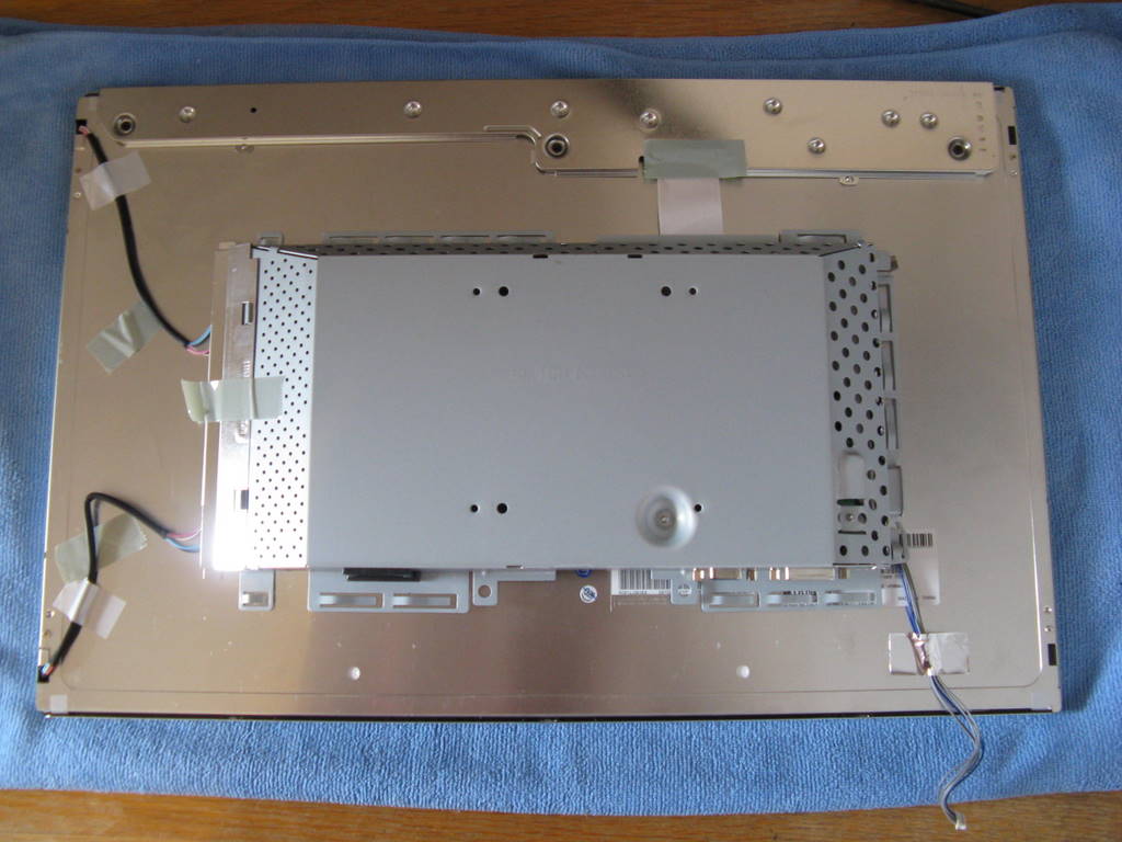
Once you've removed the plastic there are basically just two parts left, the panel and the power supply unit, which also has the video connector. Be careful not to scratch the display surface. The black back-light cables are only just long enough in the original configuration. Eventually, you'll need to carefully lengthen these.
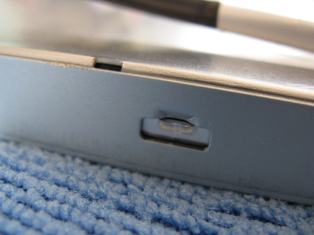
The control buttons are supported by the original casing. I just cut the whole thing out with a dremel tool.
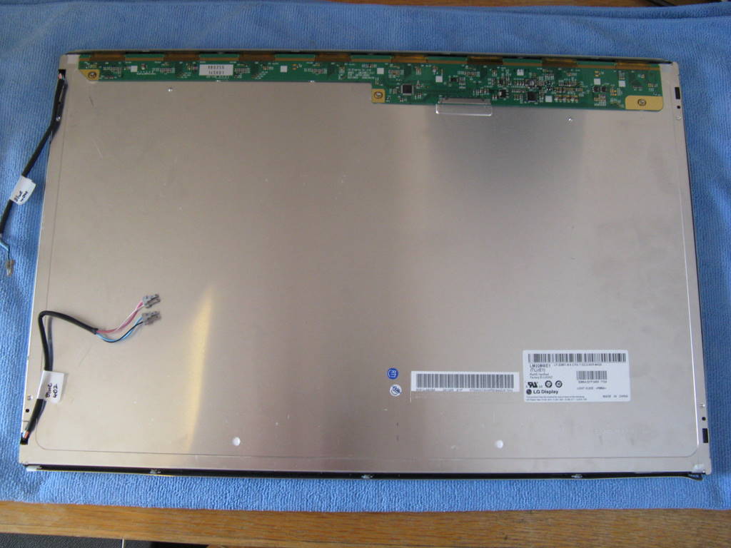
We need to separate the LCD driver board from the panel, so that we can remove the backing. Its held on by three black screws - I couldn't shift these with a screw driver and had to drill them out.
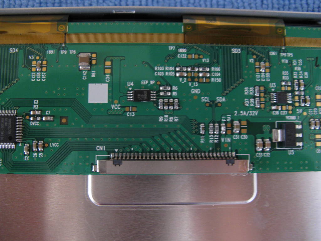
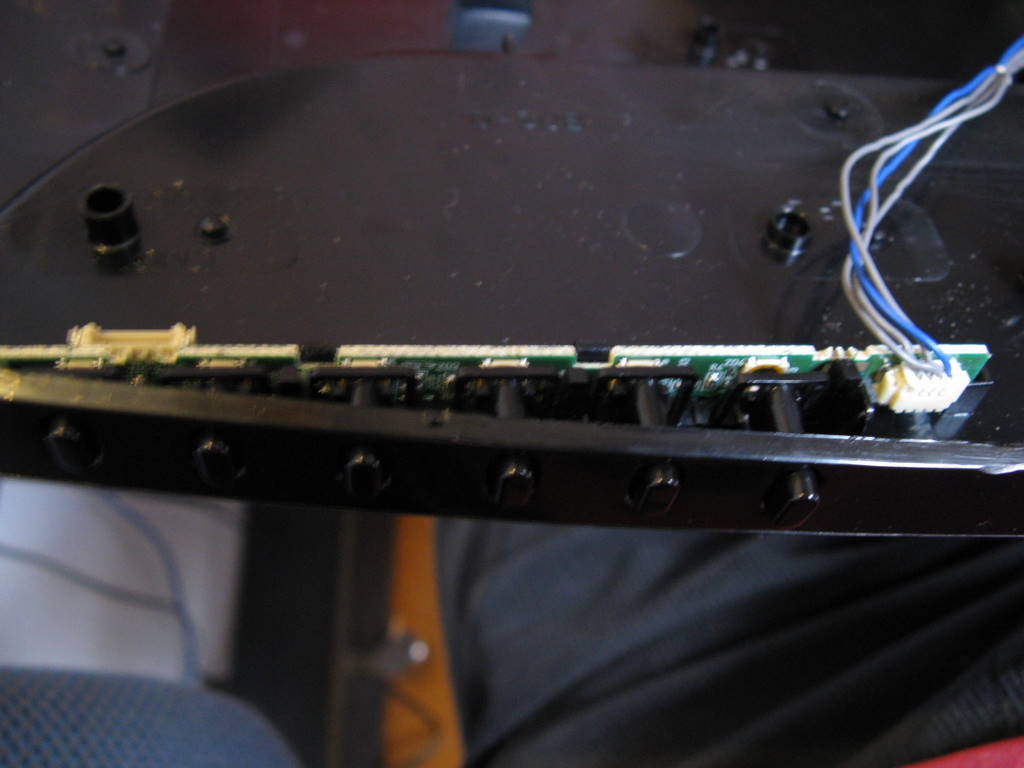
This close-up of the driver board shows the connector for the ribbon cable. Be very careful not to stress the yellow flexi cables that connect the driver to the panel. These are held on by glue, and if you tug on them they will pull off the panel and you will lose entire rows or columns of pixels. If you do damage the cables, they may be repairable, but I haven't ever tried this, so play it safe.
The metal backing is held on with clips around the edges. Carefully prise these open and you'll be able to lift the backing off. The display is made of several layers: the panel (front) with a polarising film on the front and back, a diffuser, a fresnel lens, the backlight (a perspex panel), and a glossy white plastic reflector. Most of this stuff is just to get smooth lighting of the display. I discarded the fresnel lens and the reflector, though you'll probably want to keep them until you're finished.
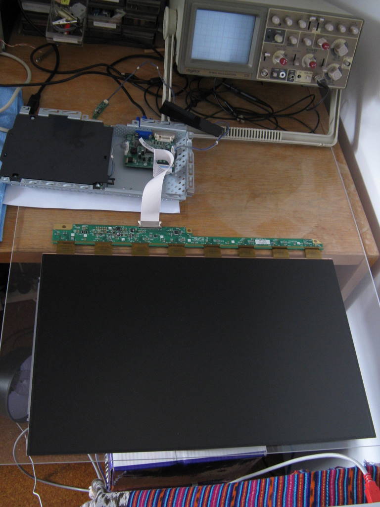
At this point you'll probably want to test the panel to make sure it still works. I set mine up on a perspex sheet. The display will still run without the backlight.
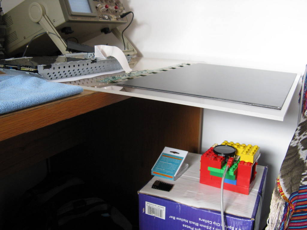
For experiments, I set up the camera under the panel in a little frame made of Duplo. You can light it from the back with a desk lamp.
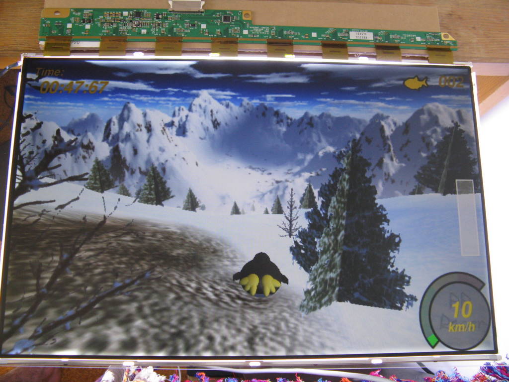
Here you can see the panel running with the original backlight.
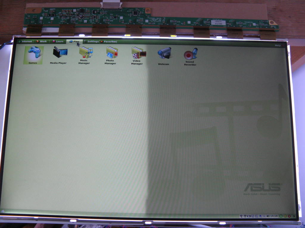
Here you can see how much brightness is lost by removing the back reflector. It makes a big difference, though the screen is usable without it. You can probably get some brightness back by lining the interior of the box with a similar glossy white coating.
Step 2: Modify the backlight
We can use the existing backlight with two modifications: cut the center out of the back, and lengthen the backlight cables.
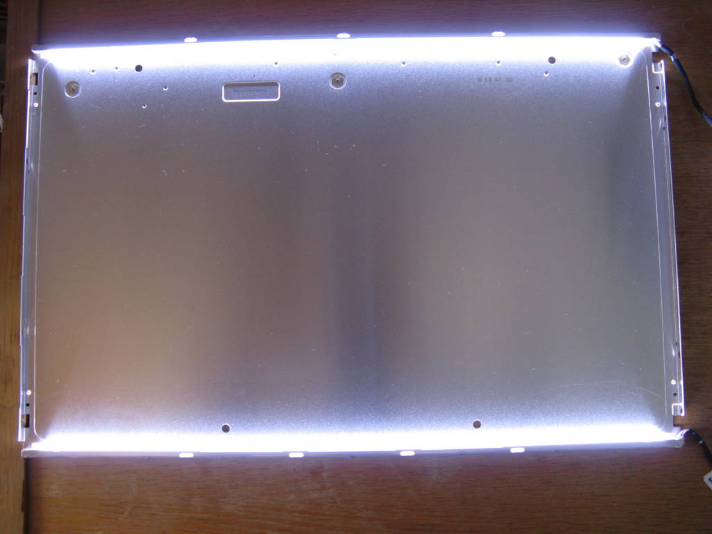
The backlight has two long fluorescent tubes, mounted in the sides of the panel. I decided to keep as much of the frame as possible, removing the center portion.
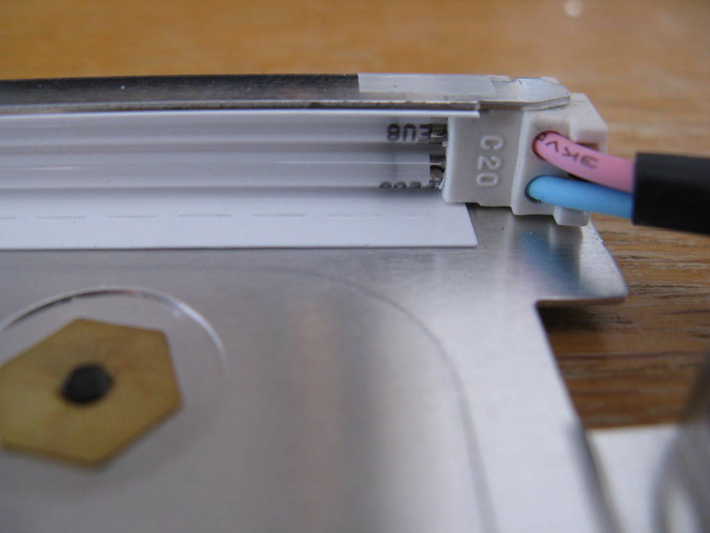
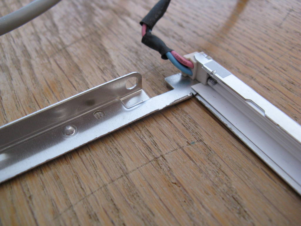
The backlight cables connect at one end of the tubes, which are supported by plastic insulators.
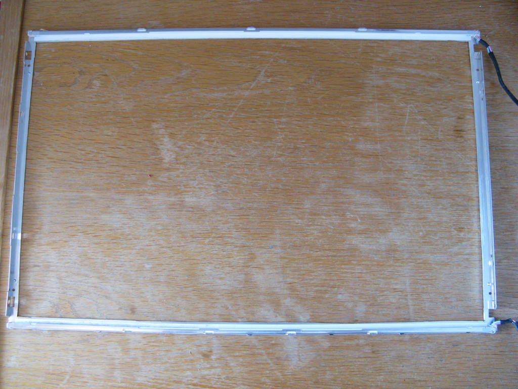
I cut the center out of the panel using a combination of hack-saw and tin snips. If you have some sort of cutting wheel that might work better. Do it carefully so you don't damage the fluoro tubes.
Try to leave some space around the corners. As you can see here, its quite thin in places. When its done, the whole LCD assembley should fit back into the frame.
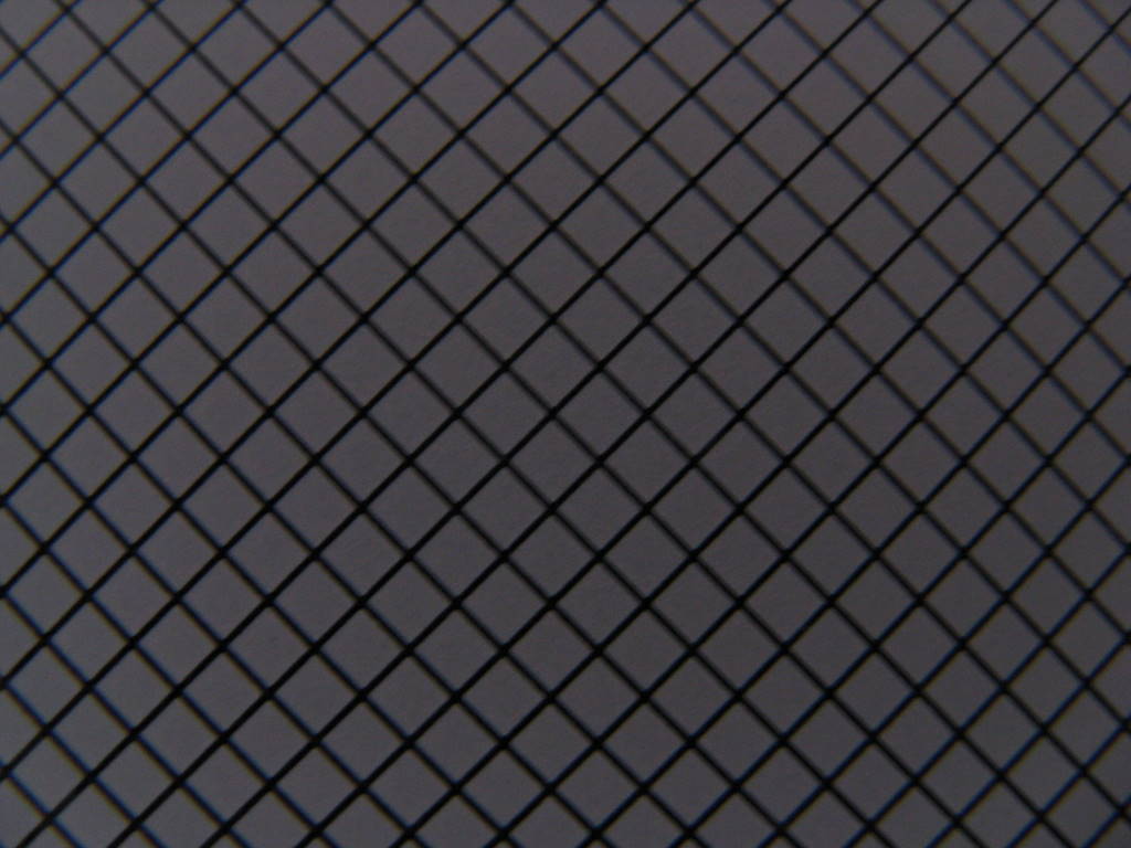
The perspex panel has an interesting pattern etched in the bottom surface. I guess this is to help reflect the light forward. Otherwise, the perspex looks quite clear, so I don't think its a diffusing edge-lit type.
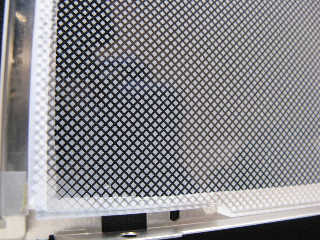
The density of the cross-hatch pattern is higher in the middle, presumably to normlise the intensity of reflected light across the surface.
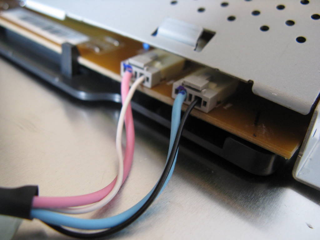
Now it time to lengthen the backlight cables. Each fluoro has two plugs (four wires). The blue and pink wires are high voltage (3kV), so you need to use a thick wire with good insulation. The power supply includes some sort of sensing that will shut down the supply if there is too much voltage drop. This means that you can't add more than about 20cm to the cable length. I cut the cables near the connector and joined the extra lengths in, insulating the joins with heat-shrink tubing.
Step 3 : Assemble the touch surface
I wanted a design that would enable sensing of objects on the surface, so I chose to use an IR diffusing surface. The top panel is 10mm edge-lit acrylic. This has a couple of brand names, including "Endlighten" and "DLux", depending on the manufacturer.
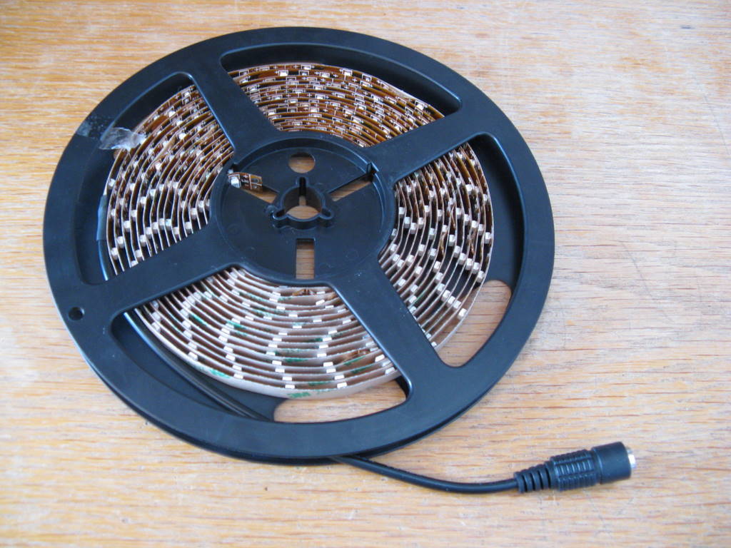
The acrylic panel is lit from the side with 850nm IR LEDs. To save time, I used 850nm IR LED Flex ribbon, from <http://www.environmentallights.com/categories/1303_2399/infrared-led-ribbon-flex">Environmental Lights. This can easily be cut to length. Its not cheap, but a 5m reel gave me enough to make two surfaces.
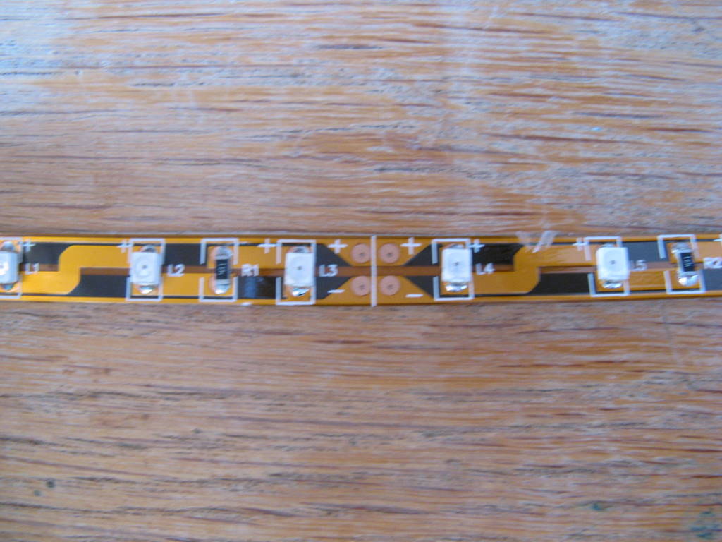
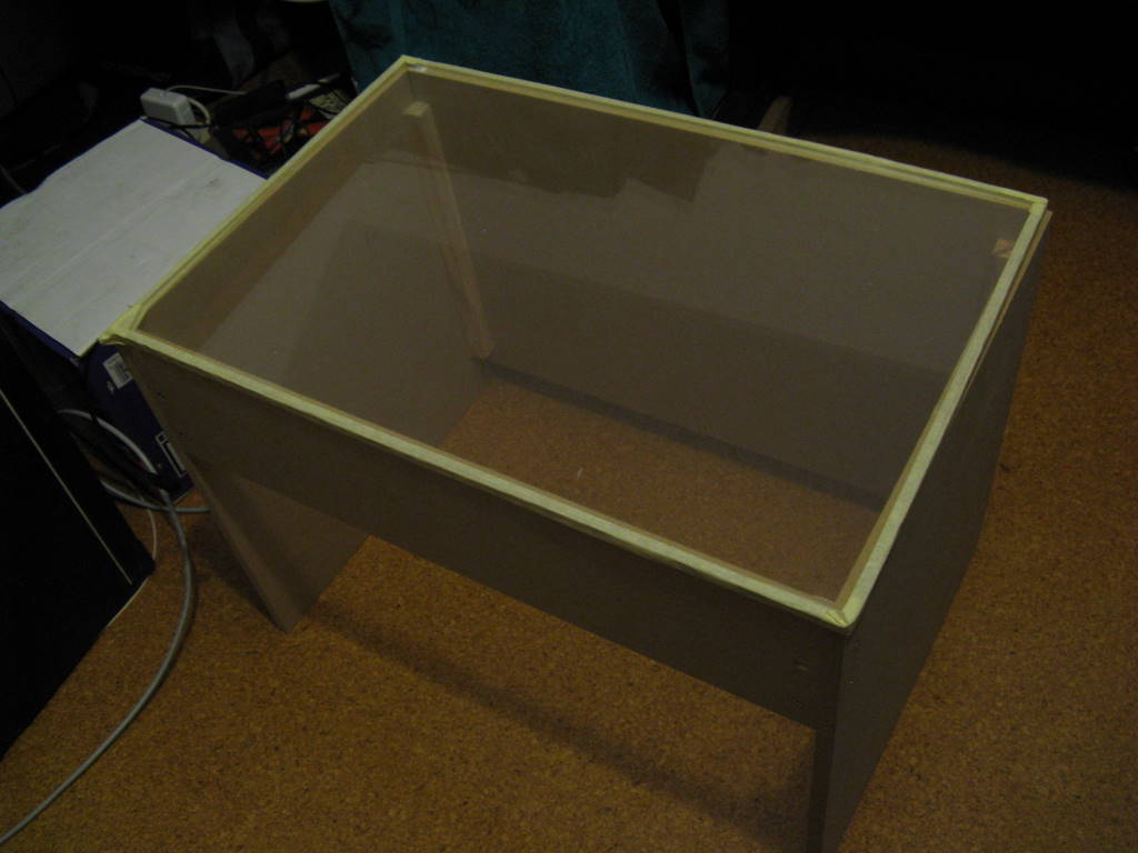
Because its flexible, the flex ribbon is very easy to attach to the panel. I just taped it on with masking tape. Here's the completed panel sitting on the beginnings of my box.
Step 4 : Putting it all together
 1.9mm lens
 |
 2.5mm lens
 |
 3.6mm lens
 |
 4.3mm lens
 |
Once I had the distance between the camera and panel, I made the box to fit. It takes a bit of juggling to get everything in the right place. Other critical distances are the distance between the power supply and the corners of the backlight, and the distance between the power supply and the driver board (for the flat ribbon cable). For safety, I chose to keep the power supply in its original shield, but the shield actually contains two small boards with a short cable between them. These could be separated if things get tight with the spacing.
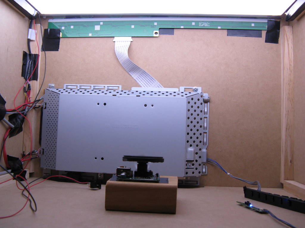
Here you can see an early side view with the camera and power supply in place.
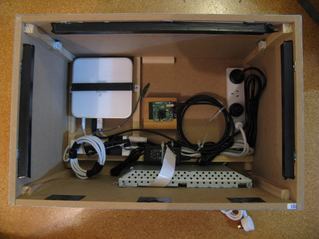
This shows a top view of the completed system, including all electronics and cabling.
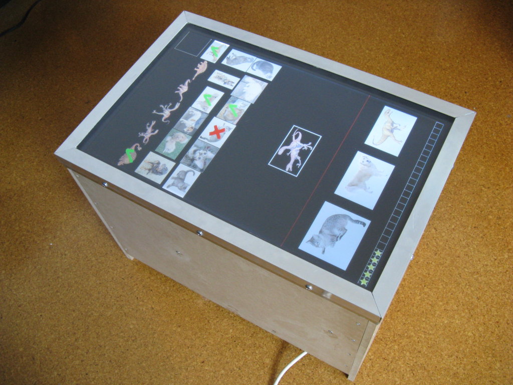
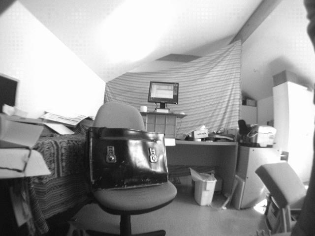
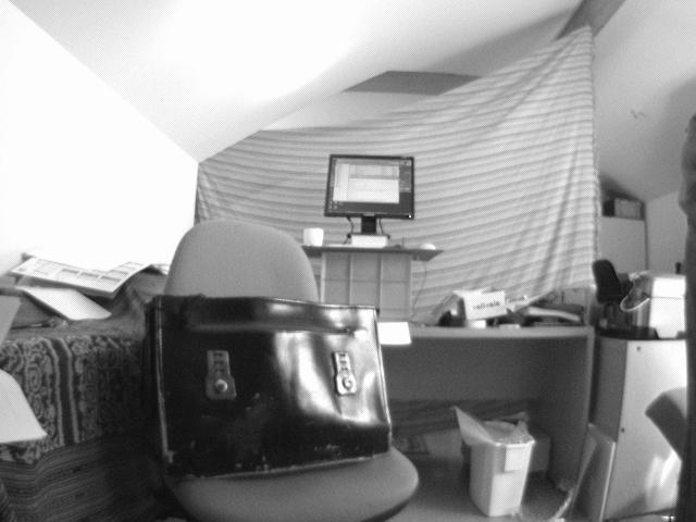
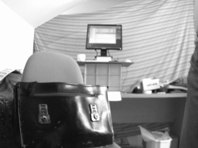
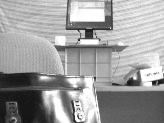
Here is the finished system up and running.
Lessons Learned
Tracking
I found the DSI surface to be surprisingly good. The contrast is low because in addition to the IR reflected from finger touches, it also receives IR diffused through the bottom surface of the acrylic, IR from the backlight, as well as ambient IR from the room. Despite the low contrast, it does seem very consistent and with appropriate settings the blob detection is reliable. If anything, it is a little too sensitive at times, responding to very light touches, brushes from sleeves, etc. It works well in normal room lighting. It does not have to be dark, though if there is bright sunlight on the surface or nearby it has some problems. Direct sunlight on the surface produces spurious blobs, and a very high ambient brightness can result in shadows and reduced sensitivity.
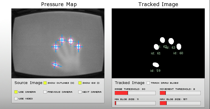
I used Community Core Vision to do the tracking. I tried the Reactivision tracker, but could get nothing but noise out of it (perhaps it doesn't work with low contrast?).
Fiducials Fail
I tried using Reactivision fiducial markers, but found the images very blurry. This blurring comes partly from the LCD panel, and partly from the diffuser.
<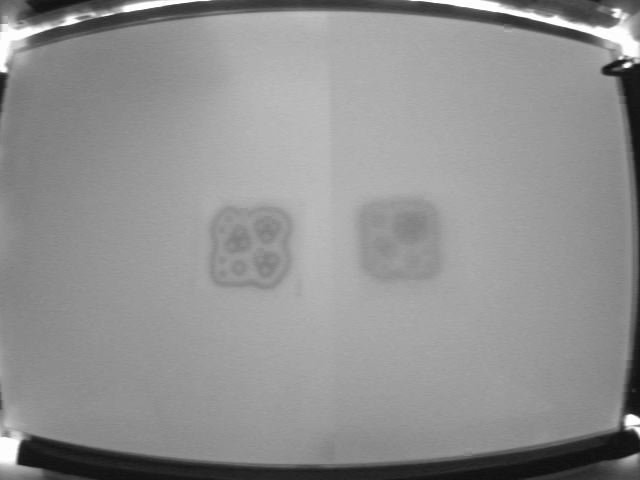
In this image, the diffuser covers only the right hand side of the display, so you can see the difference between the panel by itself (left) and with the diffuser (right). In both cases, the tracker fails to segment the fiducial from the background, though the images could possibly be recovered with some specialised signal processing, at least without the diffuser.
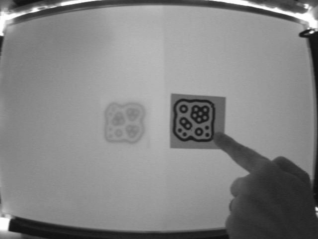
For comparison, here is the marker in front of the panel (right) and behind the panel (left).
The purpose of the diffuser is to produce a constant background illumination for the LCD panel. It does this by blurring, so this effect should not really be surprising. Without the diffuser, you can see objects behind the panel which can be confusing.
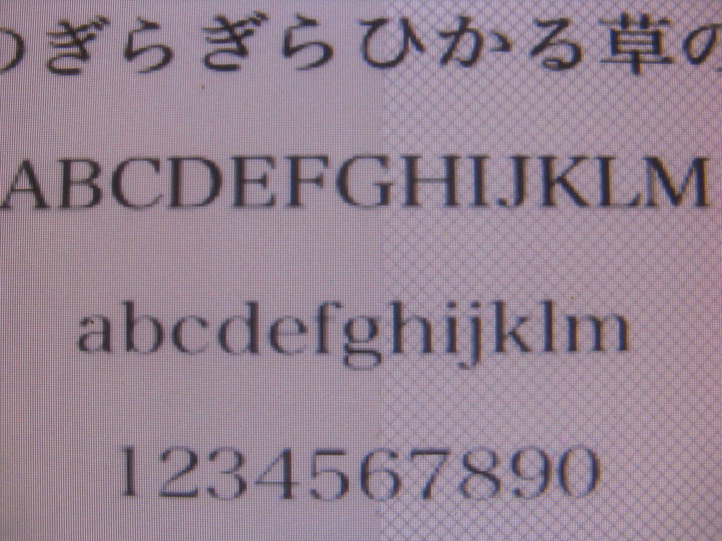
This image shows the effect on image clarity of removing the diffuser. Without the diffuser (right) we can see the cross-hatch pattern on the lower surface of the backlight. This could be improved using a different design of backlight, but then we may end up seeing through to objects behind the panel (eg. the camera and wiring). Ideally, we need a material that diffuses visible light, but transmits IR.
Anyway, although its not a showstopper, its still is an issue that I would like to solve. If anyone has any ideas or suggesions, please let me know.
Future Work
Some things still to do:
- Add cooling. With the box completely closed, it can overheat. I plan to add some inlet vents at the top, which will also let out the sound from the speakers. A fan will exhaust air out the bottom of the unit - there's a small gap between the bottom of the cabinet and the ground.
- Switch the illuminators. Currently these are always on while the unit is plugged in, but there's an activity LED from the monitor which I could easily use to switch the power to the illuminators.
- Switch the CPU. Currently need to open the table to press the power button on the Mac Mini. I don't know if the Mac can be remotely switched. I'm reluctant to hack it just yet.
- Get fiducials working.
- Write some more code! And one observation. If you leave your touch table open, it may become home to unwanted guests. I walked in today to find things wildly moving about the screen. On closer investigation I found this:
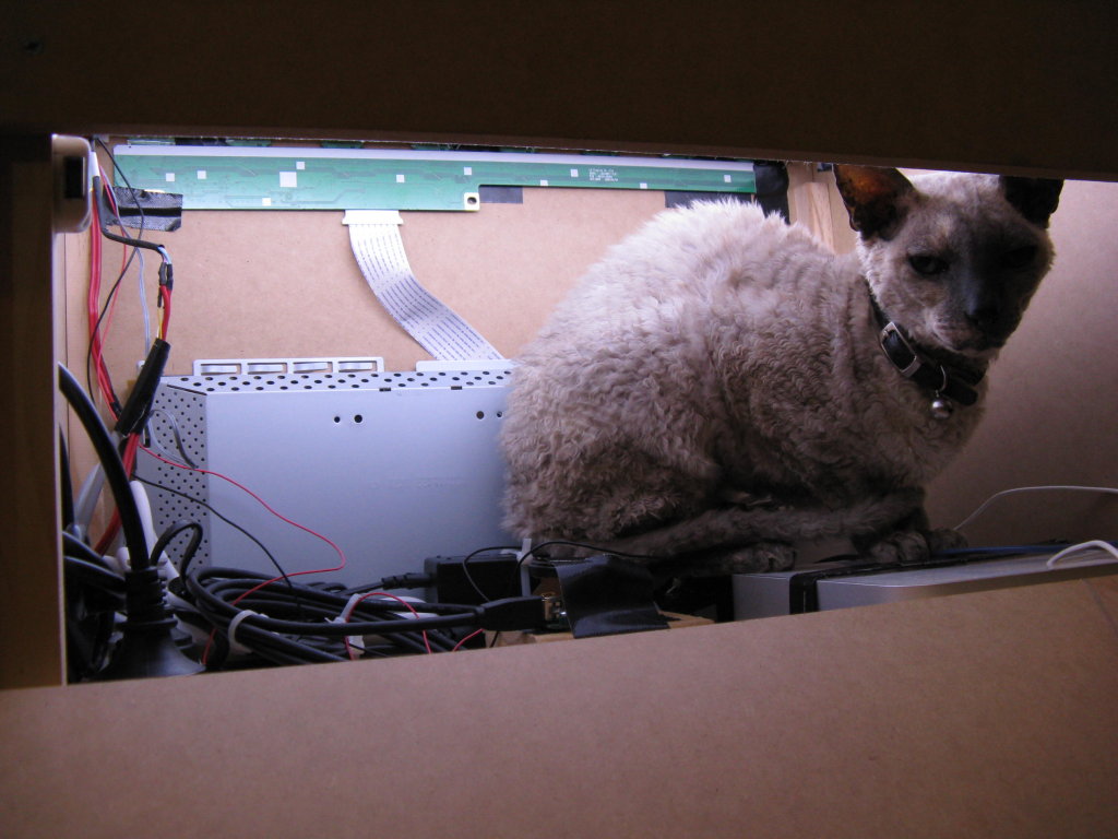
I don't blame her - its midwinter here, and for a short-haired cat, a heated box is pretty cozy place to be.